Layer Distribution controls placement of the current layer. It is important to remember that each layer's placement is also affected by its parent layer: basically layer is visible only in regions where parent layer is also visible.
Distribution Properties Group
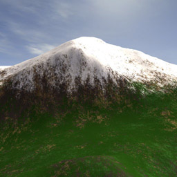
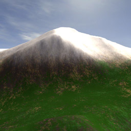
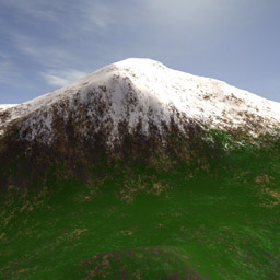
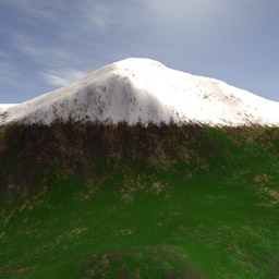
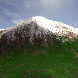
Amount - Controls opacity amount of the current layer. There is a tight connection between amount and noise, so adjust them simultaneously. Pictures below show different amounts of snow layer where noise value is left unchanged.
1. Amount 50%: Noise 17%
2. Amount 90%: Noise 17%
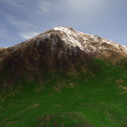
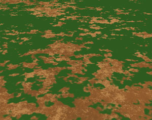
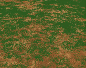
Noise - Controls how patchy the layer looks. There is a tight connection between amount and noise, so adjust them simultaneously. Noise basically controls patchiness and sharpness of layer borders.
1. Amount 84%: Noise 0%
2. Amount 84%: Noise 20%
Snow part in picture 2 above is sharper, more patchy, and transitions are less smooth than on snow in picture 1.
Feature SizeNoise Size - Controls how distinct features of the layer's shape are spread out over the terrain. This does not imply that the texture will start repeating. It only decides if noticeable bigger features will be laid out over a bigger or smaller area. Distribution 'Noise Size' is usually automatically calculated from the main Noise Size parameter. However, it can be adjusted for each layer separately for more control.
Border Detail - If border detail is off or set to 0, then layer borders will have infinite detail. This is the default behavior and works well in most cases. However, some ground materials might have lumpier look. In that case, 'Border Detail' allows you to specify the size of the smallest feature along the layer's edge.
(Tip: After increasing this value, layer edges might look too smooth. In that case, increase 'Distribution Noise' value to make edges sharper.)

No Border Detail
Small Border Detail
Large Border Detail
Altitude Limits Group - Enables user to limit the current layer by altitude (height). Altitude in GroundWiz is considered to be object's Z axis.
Note that icon for Altitude Limit Group is only a symbolic picture and doesn't represent any range since height range is not predetermined.
Min
Max - Controls minimum and maximum altitude where layer appears. Minimum number should be smaller than maximum number.Transition Height - Controls the range in which layer gradually appears or disappears. For example, transition height of 30 would mean that the transition of the selected layer happens up and down 15 meters from the altitude limit.
1. Transition Height 5
2. Transition Height 30
Slope Limits Group - Enables user to limit the current layer by slope angle of the surface. Icon of the left shows a range of angles where the selected layer will be shown (orange bar).
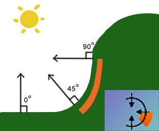
For example, the slope limit used in the picture above is set to range from 45º to 90º.
Min
Max - Controls the minimum and the maximum angle where layer appears. Angles are in degrees where 0º represents flat terrain, 90º would be a cliff, and 180º would be a cave ceiling, for example. Minimum number should be smaller than maximum number.Transition Angle - Controls slope angle range in which layer gradually appears or disappears. For example, transition angle of 10º would mean that the transition of the selected layer happens up and down 5º from the slope limit.
Direction Limits (XY plane) Group - Enables user to limit the current layer by direction in XY plane. Icon for Direction Limits shows an orange circle that represents directions where the selected layer will be shown.
It is useful for effects like limiting growth to the sunny side of the hill or something similar.
Min
Max - Controls in which directions layer appears. Minimum number should be smaller than maximum number.Transition Angle - Controls angle range in which layer gradually appears or disappears. For example, transition angle of 10º would mean that the transition of the selected layer happens up and down 5º from the slope limit.
Map Limits Group - Limits the currently selected layer's placement with any 3ds Max map. Users are able to use all 3ds Max map types, not only the most typical Bitmap for image import but also vertex color, Mix, 3d maps like noise and many others.
Many of these texture maps require objects to have UVW mapping applied which users must provide just like in any other cases.
*Hint: When you are using bitmaps and transition is too sharp, increase blurriness of edges by either blurring picture in some paint program or by using Bitmap/Coordinates/Blur offset.